Sizing a Gear Pump for a hydraulic system comes down to three interconnected variables: displacement, RPM, and flow. Get these numbers right, and the pump will deliver the actuator speed and force your machine needs without overheating, cavitating, or wasting energy. Get them wrong, and you will face sluggish operation, excessive heat, or a pump that fails long before its time.
This guide walks through the relationships between these three variables, the formulas you need, and a practical step-by-step method for selecting a Gear Pump that matches your hydraulic cylinder or motor requirements.
1. The Core Relationship: Displacement × RPM = Flow
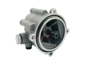
A Gear Pump is a positive displacement pump. Each revolution of the drive shaft traps and moves a fixed volume of fluid. That fixed volume is the pump’s displacement, usually expressed in cubic centimeters per revolution (cc/rev) or cubic inches per revolution (in³/rev).
Because displacement is fixed, flow is directly proportional to shaft speed. The fundamental relationship is:
Flow (theoretical) = Displacement × RPM
In metric units, the formula is commonly written as:
Q (L/min) = Vg (cc/rev) × n (RPM) ÷ 1000
where Q is flow, Vg is displacement, and n is shaft speed. In imperial units, the equivalent is:
Theoretical Flow (GPM) = RPM × CIR ÷ 231
where CIR is displacement in cubic inches per revolution. A handy metric conversion for quick field estimates is:
GPM ≈ cc/rev × RPM ÷ 3785.
These formulas are theoretical. Actual flow is lower because of internal leakage, or slip, which increases with pressure and decreases with fluid viscosity.
2. Why Theoretical Flow Is Not the Whole Story
Every Gear Pump has a volumetric efficiency, typically between 80% and 95% depending on clearances, pressure, and fluid viscosity. The actual flow delivered to the system is:
Actual Flow = Theoretical Flow × Volumetric Efficiency
If a pump has a displacement of 20 cc/rev, runs at 1,500 RPM, and has 90% volumetric efficiency, the theoretical flow is 30 L/min, but the actual flow is about 27 L/min. When sizing a Gear Pump, use actual flow—not theoretical flow—to calculate actuator speed and cycle times. Otherwise, your cylinder will move slower than expected.
3. Start with the Actuator: What Speed and Force Do You Need?
Sizing always begins with the load, not the pump. For a hydraulic cylinder, determine the required force and the required speed.
Force is set by system pressure and piston area: Force = Pressure × Piston Area. This tells you the minimum pressure the pump must sustain. Speed is set by flow and piston area: Cylinder Speed = Flow ÷ Effective Piston Area.
If the cylinder must extend at 100 mm/s and the piston area is 50 cm², the required flow is 30 L/min. If the cylinder retracts faster because the rod reduces the effective area, calculate the retraction flow separately. The higher of the two flow requirements—extension or retraction—sets the minimum pump flow.
4. Choose System Pressure and Check the Pressure Rating
The Gear Pump must be rated for the system’s maximum operating pressure, including pressure spikes. A pressure relief valve protects the pump, but the pump itself must have a continuous pressure rating above the relief setting.
Standard external gear pumps commonly operate in the 200–250 bar range, while heavy-duty and high-pressure models can reach 300 bar or more. If your cylinder requires high force, a larger bore at moderate pressure is often more efficient than a smaller bore at extreme pressure, because higher pressure increases slip and heat.
5. Select Displacement from Flow and RPM
Once you know the required flow and the available drive speed, displacement follows directly:
Displacement (cc/rev) = Required Flow (L/min) × 1000 ÷ RPM
For example, if the cylinder needs 30 L/min and the prime mover runs at 1,500 RPM, the required displacement is 20 cc/rev. If the prime mover runs at 2,000 RPM, the required displacement drops to 15 cc/rev. This is why RPM matters as much as displacement: a higher-speed drive allows a smaller, lighter, and often cheaper pump to deliver the same flow.
6. Match RPM to the Pump and the Prime Mover
Every Gear Pump has a maximum rated speed. Exceeding it accelerates wear and can cause cavitation. Running too slowly, especially with high-viscosity fluid, can reduce volumetric efficiency and starve the pump.
Typical external gear pumps for mobile and industrial use run in the 1,000–3,000 RPM range. PTO-driven pumps often run at 540 RPM, which requires a larger displacement to achieve the same flow. When selecting a Gear Pump, check three speed limits:
Maximum continuous speed set by the manufacturer.
Minimum speed required to maintain suction and lubrication.
Drive speed available from the engine, electric motor, or PTO.
If the available drive speed is fixed, displacement is your only variable. If the drive speed is flexible, choose the combination of RPM and displacement that keeps the pump within its efficient operating window.
7. Account for Viscosity and Temperature
Fluid viscosity affects both suction and slip. Cold oil is thick and hard to draw into the pump; hot oil is thin and slips past clearances, reducing volumetric efficiency. Viscous liquids may require reduced shaft speeds—often 1,150 RPM or lower—to avoid cavitation.
When sizing a Gear Pump, use the viscosity at the lowest expected operating temperature to check suction conditions, and the viscosity at the highest expected temperature to estimate slip and actual flow. If the operating temperature range is wide, a larger pump running slower may be more reliable than a small pump running fast.
8. Check Suction Conditions and Inlet Sizing
A Gear Pump cannot deliver flow it cannot draw. Suction line size, length, fittings, and fluid viscosity all affect inlet conditions. Undersized suction lines cause cavitation, noise, and damage. As a rule, keep suction velocity low and minimize bends and restrictions.
Inlet sizing is part of the sizing calculation, not an afterthought. A pump selected for the correct flow and pressure will still fail if the inlet is starved. Check the manufacturer’s recommended inlet diameter and suction conditions for the specific Gear Pump model.
9. Verify Drive Power and Torque
The prime mover must supply enough torque to drive the Gear Pump at the required pressure and speed. Hydraulic power is:
Hydraulic Power (kW) = Flow (L/min) × Pressure (bar) ÷ 600
Drive power is higher because of mechanical and volumetric losses:
Drive Power (kW) ≈ Hydraulic Power ÷ Overall Efficiency
In imperial units, a common field formula is HP = GPM × PSI ÷ 1714 ÷ efficiency. If the calculated drive power exceeds the prime mover’s available power, you must reduce flow, reduce pressure, or choose a more efficient pump.
10. A Practical Step-by-Step Sizing Example
Suppose a hydraulic cylinder must extend at 80 mm/s with a piston area of 40 cm², and the system pressure is 200 bar. The drive is an electric motor running at 1,750 RPM.
Step 1 — Required flow: 80 mm/s × 40 cm² = 32 L/min.
Step 2 — Required displacement: 32 L/min × 1000 ÷ 1750 RPM ≈ 18.3 cc/rev. Select the next standard size, for example 20 cc/rev.
Step 3 — Actual flow at 20 cc/rev and 90% efficiency: 20 × 1750 ÷ 1000 × 0.90 ≈ 31.5 L/min. This is slightly below the target, so either accept a slightly slower speed or select a 22 cc/rev pump.
Step 4 — Hydraulic power: 31.5 L/min × 200 bar ÷ 600 ≈ 10.5 kW.
Step 5 — Drive power: 10.5 kW ÷ 0.85 ≈ 12.4 kW. The motor must be rated above this value with a service margin.
This example shows how displacement, RPM, and flow interact. Changing any one variable changes the others.
11. Common Sizing Mistakes to Avoid
Using theoretical flow instead of actual flow — results in a cylinder that is slower than specified.
Ignoring retraction flow — a double-acting cylinder may require more flow to retract than to extend.
Oversizing displacement “just in case” — wastes energy, generates heat, and may require a larger reservoir and cooler.
Undersizing the suction line — causes cavitation and destroys the pump.
Matching flow but ignoring pressure — a pump can deliver the right flow at low pressure and still fail to move the load.
Forgetting viscosity and temperature — a pump sized for warm oil may not start in cold conditions.
Conclusion
Sizing a Gear Pump is not a single calculation but a chain of related decisions. Start with the actuator’s force and speed, convert those requirements into flow and pressure, then use Displacement × RPM = Flow to choose a pump that matches the prime mover. Check volumetric efficiency, pressure rating, viscosity, suction conditions, and drive power before committing to a size.
A correctly sized Gear Pump delivers the flow your cylinder needs, stays within its speed and pressure limits, and avoids the twin failures of cavitation and overheating. Whether you are specifying a log splitter gear pump, a PTO-driven gear pump, or a high-pressure gear pump for industrial service, the same three variables—displacement, RPM, and flow—govern the selection. Master their relationship, and every pump you specify will be the right one for the job.