The Directional Control Valve is the command center of any hydraulic cylinder system. It determines the path of hydraulic fluid—controlling when cylinders extend, retract, accelerate, decelerate, and hold position. Selecting the wrong Directional Control Valve can result in sluggish operation, overheating, pressure loss, or complete system failure. Conversely, the right Directional Control Valve ensures precise control, optimal efficiency, and long service life. In this comprehensive guide, we will walk you through every step of selecting the correct Directional Control Valve for your hydraulic cylinder application—covering valve types, port configurations, center positions, actuation methods, sizing criteria, and application-specific considerations.
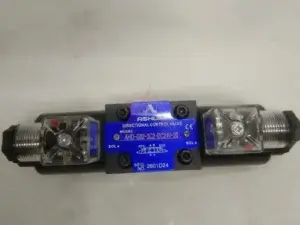
1. What Is a Directional Control Valve and Why Does It Matter?
A Directional Control Valve is a hydraulic component that directs fluid flow to different actuators—such as cylinders and motors—by opening, closing, or switching fluid paths. In a cylinder system, the Directional Control Valve determines when oil enters the piston side or the rod side, enabling extension, retraction, and stopping.
The importance of selecting the right Directional Control Valve cannot be overstated. An incorrectly sized or improperly configured valve will:
Restrict flow, reducing cylinder speed
Create excessive pressure drop, wasting energy and generating heat
Allow internal leakage, causing cylinder drift
Fail to hold position, creating safety hazards
Understanding the selection process ensures your cylinder system operates at peak performance.
2. Step 1: Determine the Required Valve Function
Before selecting a Directional Control Valve, you must define what the valve needs to do in your system.
Start/Stop Control
If your application simply requires starting and stopping fluid flow, a 2-way Directional Control Valve may be sufficient. This acts as an on-off switch, allowing flow when open and blocking it when closed.
Direction Control
For cylinder extension and retraction, you need a Directional Control Valve that can reverse flow direction. A 4-way Directional Control Valve is the standard choice for double-acting cylinders, providing independent control of extension and retraction.
Flow Path Selection
Some applications require directing flow to multiple cylinders or actuators. In these cases, a Directional Control Valve with multiple positions can select between different flow paths.
3. Step 2: Choose the Right Valve Type
Directional Control Valve types are classified based on their internal design.
Spool Valves
Spool valves are the most common type of Directional Control Valve for cylinder applications. They use a sliding cylindrical spool to open and close ports, offering smooth operation and good flow characteristics. A hydraulic spool valve is ideal for applications requiring precise cylinder positioning and proportional control.
Poppet Valves
Poppet valves use a poppet or ball to seal against a seat, providing excellent zero-leakage sealing. They are ideal for load-holding applications where the cylinder must maintain position when the Directional Control Valve is closed.
Rotary Valves
Rotary valves use a rotating element to direct flow. While less common than spool or poppet designs, they offer advantages in high-flow applications requiring a compact directional hydraulic valve.
4. Step 3: Determine the Number of Positions and Ports
The configuration of a Directional Control Valve is described by its number of ports and positions.
2-Way Valves
A 2-way Directional Control Valve has two ports and two positions (open or closed). It is essentially an on-off valve.
3-Way Valves
A 3-way Directional Control Valve has three ports and can direct flow to a single-acting cylinder while allowing exhaust.
4-Way Valves
A 4-way Directional Control Valve is the most common choice for double-acting cylinder applications. It has four ports: pressure inlet, return, and two actuator ports. This allows independent control of extension and retraction.
3-Position vs. 4-Position Valves
A 3-position Directional Control Valve includes a center position that can be configured for different functions. A 4-position valve offers additional flow path options for complex circuits. For controlling double-acting cylinders with mid-position stopping capability, a 4-way, 3-position valve is the most common choice.
5. Step 4: Select the Center Position Configuration
The center position of a 3-position Directional Control Valve significantly impacts system behavior.
Closed Center
In a closed center Directional Control Valve, all ports are blocked in the neutral position. This holds cylinder position and maintains pressure. Ideal for applications requiring load holding and precise positioning.
Tandem Center
In a tandem center Directional Control Valve, the actuator ports are blocked while the pressure port connects to the return port. This allows the pump to unload when the valve is centered, providing energy efficiency while maintaining some pressure.
Open Center
In an open center Directional Control Valve, all ports are connected in the neutral position, allowing fluid to circulate freely. Common in mobile equipment where continuous pump flow is required.
Regenerative Center
A regenerative center Directional Control Valve connects pressure to both actuator ports in neutral, allowing faster cylinder extension using regeneration.
6. Step 5: Select the Actuation Method
The actuation method determines how the Directional Control Valve is operated.
Manual Actuation
Manual valves use levers, handles, push buttons, or foot pedals. A manually operated Directional Control Valve is simple, reliable, and cost-effective for applications where the operator is physically present.
Solenoid Actuation
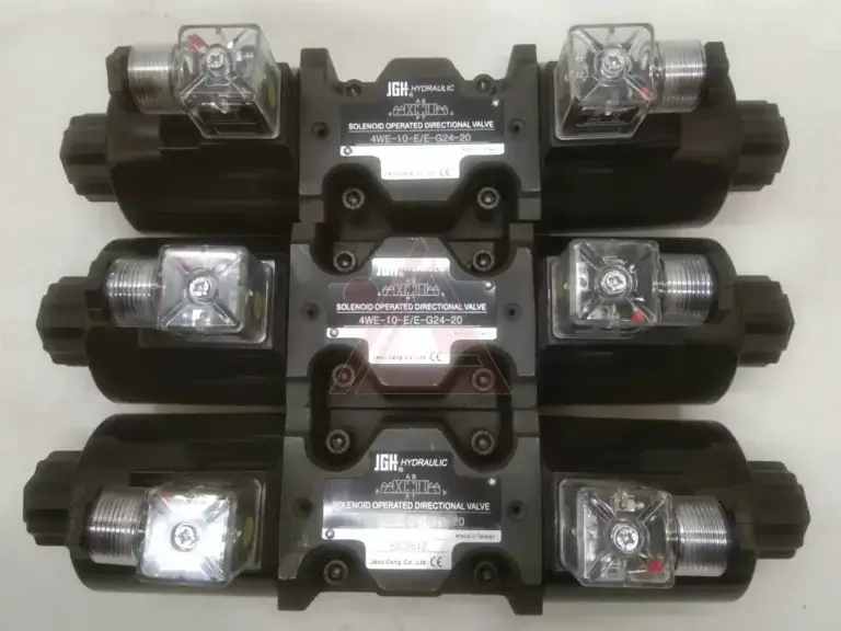
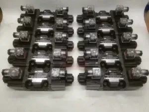
Solenoid-operated valves use electrical signals to shift the valve spool. A hydraulic solenoid valve enables remote control, automation, and fast response times—ideal for PLC-controlled systems and automated cylinder sequencing.
Pilot Actuation
Pilot-operated valves use hydraulic or pneumatic pressure to shift the valve. They are used in high-flow applications where solenoid forces are insufficient, or where explosion-proof operation is required.
Proportional Actuation
Proportional valves provide variable control of flow and pressure based on an electrical input signal. They enable smooth cylinder acceleration and deceleration, reducing shock loads and improving positioning accuracy.
7. Step 6: Calculate Flow Rate and Pressure Requirements
Proper sizing of the Directional Control Valve is essential for optimal cylinder performance.
Flow Rate Calculation
Calculate the flow rate required for your cylinder: Flow Rate = Piston Area × Velocity. The Directional Control Valve must handle this flow without excessive pressure drop. Undersizing restricts flow and reduces cylinder speed; oversizing adds unnecessary cost.
Pressure Rating
The Directional Control Valve must be rated for your system’s maximum operating pressure. Select a valve with a pressure rating at least 10–20% higher than your system’s peak pressure to provide a safety margin.
8. Step 7: Evaluate Valve Performance Characteristics
Several performance characteristics of the Directional Control Valve affect cylinder system operation.
Pressure Drop
Every Directional Control Valve creates some pressure drop. Lower pressure drop means less energy loss and less heat generation. For high-flow applications, select a valve with low pressure drop characteristics.
Leakage Rate
Internal leakage in a Directional Control Valve can cause cylinder drift. Spool valves typically have minimal internal leakage; poppet valves offer zero-leakage sealing for critical load-holding applications.
Response Time
The time it takes for a Directional Control Valve to shift affects system responsiveness. Solenoid valves generally offer faster response than manual or pilot-operated valves.
9. Step 8: Choose the Right Mounting Configuration
The mounting method affects installation, maintenance, and system layout.
Subplate Mounting
Subplate-mounted valves are bolted to a subplate containing port connections. This is the most common mounting for industrial valves, allowing easy replacement without disturbing piping.
Threaded Connections
Threaded valves have ports that accept pipe fittings. Commonly used in mobile equipment and smaller systems where space is limited.
Cartridge Valves
Cartridge valves are inserted into a cavity in a manifold block, offering compact, space-saving installation. Widely used in mobile and industrial applications.
10. Step 9: Consider the Operating Environment
The operating environment significantly impacts Directional Control Valve performance and life.
Temperature Range
Ensure valve seals and materials are compatible with your operating temperature range. Special seals such as Viton may be required for high-temperature applications.
Contamination Resistance
Directional control valves with tighter clearances require cleaner fluid. Select valves with appropriate contamination tolerance for your system.
Corrosion Resistance
For marine or chemical applications, select valves with corrosion-resistant materials such as stainless steel or special coatings.
11. Common Mistakes to Avoid
Avoid these common errors when choosing a Directional Control Valve:
Undersizing: Restricts flow, reduces speed, and causes overheating.
Oversizing: Adds unnecessary cost and may reduce controllability.
Ignoring Center Position: The center position configuration significantly affects system behavior.
Mismatching Actuation: Select an actuation method that matches your control requirements and environment.
Neglecting Pressure Drop: High pressure drop wastes energy and generates heat.
12. Application Examples
Directional Control Valve selection varies by application:
Mobile Equipment: 4-way, open center valve with manual or pilot actuation.
Industrial Presses: 4-way, closed center valve with solenoid actuation.
Agricultural Machinery: 4-way, tandem center valve with pilot or manual actuation.
Material Handling: 4-way valve with solenoid actuation and subplate mounting.
Conclusion
Selecting the right Directional Control Valve for your hydraulic cylinder system requires careful consideration of valve function, type, port configuration, center position, actuation method, flow rate, pressure rating, performance characteristics, mounting style, and environmental factors. Whether you need a hydraulic spool valve, a hydraulic solenoid valve, or a directional hydraulic valve with pilot actuation, understanding these selection criteria ensures optimal cylinder performance, energy efficiency, and long system life. By following this comprehensive guide, you can confidently select the correct Directional Control Valve for your specific application.