A Hydraulic Gear Pump is one of the most common and widely used types of hydraulic pumps in industrial and mobile applications. It is a positive displacement pump that uses the meshing of gears to pump fluid by displacement. Understanding what is a hydraulic gear pump and how it works is essential for anyone involved in hydraulic system design, maintenance, or operation. In this comprehensive guide, we will explore the definition, working principle, key components, types, applications, and maintenance of the Hydraulic Gear Pump.
1. What Is a Hydraulic Gear Pump? Basic Definition
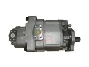
A Hydraulic Gear Pump is a positive displacement pump that uses two or more gears to transfer fluid from the inlet to the outlet. As the gears rotate, they trap fluid between the gear teeth and the pump housing, then carry it to the discharge side. The pump delivers a fixed volume of fluid per revolution, making it a fixed displacement pump. This characteristic makes the Hydraulic Gear Pump ideal for applications where a constant flow rate is required.
The Hydraulic Gear Pump is known for its simple construction, high reliability, and cost-effectiveness. It can handle pressures up to 3,000 psi (210 bar) and is widely used in construction equipment, agricultural machinery, material handling systems, and industrial manufacturing.
2. How Does a Hydraulic Gear Pump Work? The Basic Principle
To understand what is a hydraulic gear pump and how it works, you need to grasp its fundamental operating principle. The pump operates on the displacement principle: as the gears rotate, fluid is drawn into the pump through the inlet port and trapped between the gear teeth and the housing. The fluid is then carried around the outside of the gears to the outlet port, where it is forced out under pressure.
The rotating gears create a partial vacuum at the inlet, which draws fluid into the pump. The fluid fills the spaces between the gear teeth and is transported to the outlet side. As the gears mesh together, the fluid is displaced and pushed out through the outlet port. This continuous process creates a steady flow of hydraulic fluid.
3. Key Components of a Hydraulic Gear Pump
A typical Hydraulic Gear Pump consists of the following key components:
Housing: The outer casing that encloses the gears and contains the fluid.
Drive Gear (Input Gear): The gear connected to the power source (electric motor or engine).
Driven Gear (Output Gear): The gear that meshes with the drive gear and rotates in the opposite direction.
Inlet Port: Where fluid enters the pump from the reservoir.
Outlet Port: Where pressurized fluid exits the pump to the hydraulic system.
Bushings or Bearings: Support the gear shafts and reduce friction.
Seals: Prevent internal and external leakage.
4. Types of Hydraulic Gear Pumps
There are two main types of Hydraulic Gear Pump: external gear pump and internal gear pump.
External Gear Pump
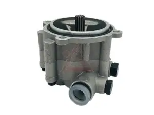
An external gear pump uses two identical gears of the same size that mesh externally. One gear is the drive gear, and the other is the driven gear. As they rotate, fluid is trapped between the gear teeth and the housing, then carried from the inlet to the outlet. External gear pumps are the most common type of Hydraulic Gear Pump and are widely used in mobile and industrial applications.
Internal Gear Pump
An internal gear pump uses one larger gear with internal teeth and a smaller external gear that rotates inside it. The fluid is trapped between the gear teeth and a crescent-shaped separator. Internal gear pumps offer quieter operation and better suction capabilities compared to external gear pumps.
5. Working Cycle of a Hydraulic Gear Pump
The working cycle of a Hydraulic Gear Pump can be broken down into three phases:
Suction Phase: As the gears rotate away from the inlet port, a vacuum is created, drawing fluid into the pump. Fluid fills the spaces between the gear teeth.
Transport Phase: The fluid is carried around the outside of the gears, trapped between the gear teeth and the housing. The fluid moves from the inlet side to the outlet side.
Discharge Phase: As the gears mesh together at the outlet port, the fluid is displaced and forced out of the pump through the outlet port under pressure.
6. Key Performance Parameters
When selecting a Hydraulic Gear Pump, several performance parameters must be considered:
Displacement: The volume of fluid delivered per revolution (cubic inches or cubic centimeters per revolution).
Flow Rate: The volume of fluid delivered per minute (gallons per minute or liters per minute).
Pressure Rating: The maximum pressure the pump can safely handle (psi or bar).
Speed: The rotational speed of the pump (RPM).
Efficiency: Volumetric efficiency and mechanical efficiency.
7.Applications of Hydraulic Gear Pumps
The Hydraulic Gear Pump is used in a wide range of applications across many industries:
Construction Equipment: Excavators, loaders, bulldozers, and cranes.
Agricultural Machinery: Tractors, combines, sprayers, and harvesters.
Material Handling: Forklifts, conveyors, and lift tables.
Industrial Manufacturing: Presses, injection molding machines, and machine tools.
Automotive: Power steering systems, lifts, and hydraulic jacks.
Marine: Steering systems, winches, and deck machinery.
8. Advantages and Disadvantages
Advantages of Hydraulic Gear Pumps
Simple and robust construction.
High reliability and long service life.
Cost-effective compared to other pump types.
Tolerant to contamination (more than piston pumps).
Wide range of sizes and configurations available.
Self-priming capability.
Disadvantages of Hydraulic Gear Pumps
Fixed displacement (cannot vary flow rate without speed change).
Less efficient than piston pumps at high pressures.
Can be noisy at high speeds.
Not suitable for very high pressure applications (above 3,000 psi).
9. How to Select the Right Hydraulic Gear Pump
Choosing the right Hydraulic Gear Pump for your application requires consideration of several factors:
Flow Rate Requirements: Calculate the flow needed to achieve desired actuator speeds.
Pressure Requirements: Determine the maximum pressure your system will require.
Speed: Match the pump’s speed rating to your power source.
Fluid Compatibility: Ensure the pump materials are compatible with your hydraulic fluid.
Mounting Configuration: Select the appropriate mounting style (flange, foot, or direct).
Environmental Conditions: Consider temperature, contamination, and noise constraints.
10. Maintenance Tips for Hydraulic Gear Pumps
Proper maintenance extends the service life of a Hydraulic Gear Pump:
Keep Fluid Clean: Contamination is the leading cause of pump failure. Use proper filtration.
Monitor Fluid Temperature: Overheating degrades fluid and damages components.
Check Inlet Conditions: Ensure suction lines are not restricted or leaking air.
Inspect for Leaks: Check seals and connections regularly.
Listen for Unusual Noises: Cavitation or bearing wear often produce distinctive sounds.
Change Filters Regularly: Replace return line and suction filters at recommended intervals.
Conclusion
A Hydraulic Gear Pump is a simple, reliable, and cost-effective positive displacement pump that converts mechanical energy into hydraulic power. Understanding what is a hydraulic gear pump and how it works is essential for anyone working with hydraulic systems. Whether you choose an external gear pump for its simplicity and durability or an internal gear pump for quieter operation, the Hydraulic Gear Pump remains a fundamental component in countless industrial and mobile applications. By selecting the right pump and maintaining it properly, you can ensure reliable, efficient operation for years to come.