Flow control is one of the most critical aspects of hydraulic system design. It determines the speed of cylinders and motors, the rate of energy transfer, and ultimately the productivity of the machine. Without proper flow control, hydraulic actuators would move erratically, loads would be difficult to position, and energy would be wasted.
Flow control valves are any device manufactured for the purpose of modifying the rate of fluid flow in a portion of a hydraulic circuit. By regulating flow rate, these valves directly control the speed of hydraulic cylinders and motors. Understanding the various types of flow control valves helps engineers, maintenance technicians, and equipment operators select the right component for their hydraulic system.
In this comprehensive guide, we will explore the major types of flow control valves used in hydraulic systems—including orifices, flow regulators, bypass regulators, demand-compensated controls, pressure-compensated valves, temperature-compensated valves, priority valves, and deceleration valves—along with their working principles, applications, and selection criteria. There are eight different types of flow control valves commonly used in hydraulic systems.
1. What Is a Flow Control Valve and Why Is It Important?
Before diving into the specific types of flow control valves, it is important to understand what these valves do. A flow control valve is a hydraulic component that regulates the volume of fluid passing through a circuit per unit of time. By controlling flow rate, these valves directly control the speed of hydraulic cylinders and motors.
Flow rate determines the speed of an actuator. The relationship is straightforward: actuator speed is a function of flow rate. If you need a cylinder to extend faster, you increase the flow rate; to slow it down, you reduce the flow. This is why understanding the types of flow control valves is fundamental to hydraulic system design and troubleshooting.
2. Orifices: The Simplest Flow Control
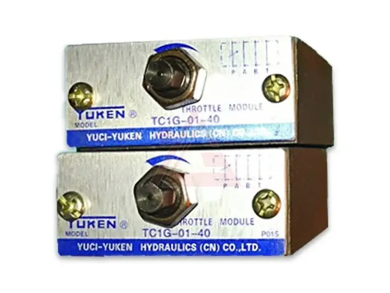
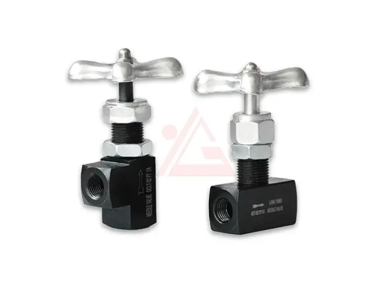
The most elementary types of flow control valves is the orifice. An orifice is simply a restriction in the hydraulic line—a drilled hole in a fitting or a calibrated opening that limits flow. Orifices can be fixed (a hole of constant size) or variable (such as a needle valve that allows adjustment).
How Orifices Work: When fluid passes through an orifice, the pressure drops across the restriction. The smaller the orifice, the greater the pressure drop and the lower the flow rate. This basic principle makes orifices the foundation of all other types of flow control valves.
Applications and Limitations: Orifices are simple, inexpensive, and reliable. However, they are non-compensated flow control devices. This means the flow rate through an orifice changes when system pressure fluctuates. As pressure increases, flow increases; as pressure drops, flow decreases. This makes orifices unsuitable for applications requiring consistent speed under varying loads.
3. Flow Regulators: Improved Accuracy
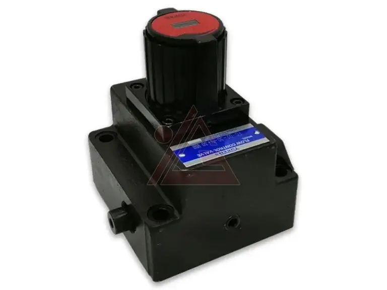
Flow regulators are a step up from simple orifices among the types of flow control valves. They consist of an orifice that senses flow rate as a pressure drop, combined with a compensating piston that adjusts to variations in inlet and outlet pressures.
How Flow Regulators Work: The compensating piston automatically adjusts the orifice size to maintain a more consistent flow rate under varying pressure conditions. This provides closer control of flow rate, typically with accuracy of about 5%.
Applications: Flow regulators are used in applications where moderate speed control accuracy is sufficient, such as in machine tools, lift tables, and elevating platforms.
4. Bypass Flow Regulators: Improved Efficiency
Bypass flow regulators represent a more efficient design among the types of flow control valves. In these valves, flow in excess of the set flow rate returns to the reservoir through a bypass port.
How Bypass Flow Regulators Work: Flow rate is controlled by throttling fluid across a variable orifice regulated by the compensator piston. Instead of forcing all excess flow through the control orifice, the bypass returns it to the tank, reducing energy waste.
Applications: Bypass flow regulators are ideal for systems where energy efficiency is important, such as in mobile equipment and hydraulic power units.
5. Demand-Compensated Flow Controls: Secondary Circuit Supply
Demand-compensated flow controls are unique types of flow control valves that can bypass excess system flow to a secondary circuit. Fluid is routed at a controlled flow rate to the primary circuit, and bypass fluid can be used for work functions in secondary circuits without affecting the primary one.
How They Work: These valves require flow to the primary circuit to function. If the primary circuit is blocked, the valve will cut off flow to the secondary circuit. During the idle portion of the work cycle, the valve bypasses full pump output to the tank.
Applications: Demand-compensated flow controls are used in complex hydraulic systems where multiple functions must operate simultaneously, such as in excavators and agricultural machinery.
6. Pressure-Compensated Flow Control Valves
Pressure compensated flow control valves are among the most important types of flow control valves for applications requiring consistent actuator speed regardless of load changes. A pressure compensated flow control valve is designed to provide a constant volume flow rate regardless of the pressure drop across it.
How Pressure-Compensated Valves Work: These valves combine a variable orifice with a pressure compensator in one valve body. The variable orifice determines the flow cross-section. As oil flows through the orifice, a pressure drop occurs. The pressure compensator moves to maintain a constant pressure drop across the variable orifice, keeping the flow rate constant. The pressure compensator maintains the valve’s set pressure drop by comparing upstream and downstream pressure and then varies the orifice to maintain desired flow.
When flow rate increases, the pressure compensator reduces the diameter of the control orifice until the forces are equal again. This ensures a constant flow rate regardless of pressure variations in the system.
Applications: Pressure-compensated flow control valves are used in applications where cylinder speed must remain constant under varying loads, such as in machine tools, plastic injection molding machines, hydraulic presses, and mobile equipment with varying load conditions.
Key Features: These valves can achieve control accuracies of 3% to 5%. They are available with integral reverse-flow check valves (allowing unrestricted flow in the opposite direction) and integral overload relief valves.
7. Pressure- and Temperature-Compensated Flow Control Valves
Temperature changes affect hydraulic fluid viscosity, which in turn affects flow control accuracy. Pressure and temperature compensated flow control valves address this by adding temperature compensation to pressure compensation.
How They Work: Temperature compensators adjust the control orifice openings to correct the effects of viscosity changes caused by temperature fluctuations. This ensures consistent flow control across a wide range of operating temperatures.
Applications: These valves are used in applications where temperature variations are significant, such as outdoor mobile equipment operating in extreme weather conditions.
8. Priority Valves
Priority valves are specialized types of flow control valves that supply a constant flow rate to a primary circuit regardless of changes in inlet pressure, while diverting excess flow to a secondary circuit.
How Priority Valves Work: A priority valve maintains a fixed flow to the priority (primary) port. Excess flow beyond the priority flow is directed to the secondary (excess) port. This ensures that critical functions always receive the flow they need, even when system conditions change.
Applications: Priority valves are commonly used in steering circuits in mobile equipment (steering always gets priority), brake systems, and pilot control circuits. Pressure-compensated priority flow control valves can maintain constant flow regardless of changes to inlet pressure.
9. Deceleration Valves
Deceleration valves are types of flow control valves designed to gradually reduce the speed of a cylinder as it approaches the end of its stroke. This prevents impact and reduces shock loads on the system.
How Deceleration Valves Work: These valves progressively restrict flow as the cylinder reaches the end of its travel, creating a controlled deceleration. This protects both the cylinder and the machine from damaging impacts.
Applications: Deceleration valves are used in high-speed presses, injection molding machines, and any application where cylinders travel at high speed and need to stop smoothly.
10. Flow Control Circuits: Meter-In, Meter-Out, and Bleed-Off
Beyond individual valve types, understanding the types of flow control valves also involves knowing how they are applied in circuits. Three types of flow control circuits are most common: meter-in, meter-out, and bleed-off (sometimes called bypass).
Meter-In Control: Flow control is placed on the inlet side of the actuator, controlling the flow entering the cylinder. This is suitable for applications where the load opposes the direction of movement (e.g., extending against a resistance).
Meter-Out Control: Flow control is placed on the outlet side, restricting the flow leaving the cylinder. This provides better control for overrunning loads where the load pulls the cylinder.
Bleed-Off (Bypass) Control: Flow is controlled by bypassing a portion of the pump flow to the tank before it reaches the actuator. This is the most energy-efficient method for constant-speed applications.
11. Selecting the Right Flow Control Valve
Choosing from the various types of flow control valves requires consideration of several factors:
Application Requirements: Determine the level of speed control accuracy needed.
Load Conditions: Consider whether loads are constant or variable.
Pressure Fluctuations: If system pressure varies, choose pressure-compensated valves.
Temperature Variations: If temperature changes are significant, choose temperature-compensated valves.
Energy Efficiency: Consider whether bypass or bleed-off circuits are appropriate.
Flow Rate: The valve must handle the required flow without excessive pressure drop.
Conclusion
Understanding the various types of flow control valves is essential for designing, operating, and maintaining efficient hydraulic systems. From simple orifices to sophisticated pressure-compensated flow control valves, each type of flow control valve serves a specific function in controlling actuator speed. The pressure compensated flow control valve provides constant flow regardless of load changes, while the flow regulator valve offers improved accuracy over simple orifices. The priority flow control valve ensures critical functions always receive the flow they need. By selecting the right valve for your application and understanding the different flow control circuits—meter-in, meter-out, and bleed-off—you can achieve precise speed control, maximize energy efficiency, and extend the service life of your hydraulic system.