A Directional Control Valve is one of the most essential components in any hydraulic system. It serves as the command center that directs the flow of hydraulic fluid to different actuators—cylinders, motors, or other devices—by opening, closing, or switching fluid pathways. Without a Directional Control Valve, hydraulic systems would be unable to perform the precise movements required in modern machinery. Whether you are operating an excavator, a hydraulic press, or an agricultural tractor, the Directional Control Valve is the component that determines when and how work gets done.
In this comprehensive guide, we will explore what a Directional Control Valve is, how it works, its core components, the different types available, and its essential role in hydraulic systems. Understanding the function of a Directional Control Valve is fundamental for anyone involved in hydraulic system design, maintenance, or operation.
1. What Is a Directional Control Valve? Basic Definition
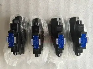
A Directional Control Valve is a mechanical device that controls the direction of hydraulic fluid flow within a hydraulic system. It is essentially the traffic controller of the system, directing fluid to actuators such as cylinders and motors to perform specific tasks. A Directional Control Valve can start, stop, or regulate fluid flow, control pressure levels, and determine the direction of fluid movement. By doing so, a Directional Control Valve enables precise control over the speed, force, and position of hydraulic actuators.
The most common Directional Control Valve configurations are 2-way, 3-way, and 4-way valves. For double-acting cylinder applications, a 4-way Directional Control Valve is typically required. This configuration allows fluid to be directed to either side of the piston while the opposite side exhausts to the reservoir. Without a Directional Control Valve, the fluid would simply circulate without performing useful work, making it an indispensable component in any hydraulic circuit.
2. How Does a Directional Control Valve Work?
Understanding how a Directional Control Valve works requires a basic knowledge of hydraulic principles. A Directional Control Valve operates by creating restrictions or openings in the fluid path. When the valve spool or poppet is moved, it changes the flow path of the hydraulic fluid. This movement can be controlled manually, mechanically, electrically, or hydraulically.
The Basic Operating Principle
The operating principle of a Directional Control Valve is based on the concept of fluid routing. The valve contains internal passages that connect different ports. When the valve is in its neutral position, these passages are arranged so that fluid flows in a specific pattern—depending on the valve type, this might be a closed center, open center, or tandem center configuration.
When the Directional Control Valve is actuated—either by moving a lever, energizing a solenoid, or applying pilot pressure—the spool shifts position, creating a new set of connections between the ports. Fluid is then routed to the actuator, causing it to move.
Example: Controlling a Double-Acting Cylinder
For example, when a Directional Control Valve is actuated in one direction, it shifts the spool position, directing fluid to one side of a cylinder while allowing fluid from the other side to return to the reservoir. This movement causes the cylinder to extend. When the valve is actuated in the opposite direction, it redirects fluid to the other side of the cylinder, causing it to retract. The Directional Control Valve can also be placed in a neutral position where all ports are blocked, holding the cylinder in position.
Internal Leakage Considerations
The performance of a Directional Control Valve is also affected by internal leakage. Spool valves typically have some internal clearance, resulting in minimal leakage. Poppet valves offer zero-leakage sealing, making them ideal for load-holding applications where the cylinder must maintain position when the valve is closed.
3. Key Components of a Directional Control Valve
A typical Directional Control Valve consists of several key components:
Valve Body: The outer housing that contains the internal components and provides connection points for hydraulic lines. It is typically made of cast iron, steel, or aluminum.
Spool or Poppet: The moving element that opens, closes, or partially obstructs flow paths. In a hydraulic spool valve, the spool slides within the body to direct flow; in a poppet valve, a poppet lifts off a seat to allow flow.
Actuator Mechanism: The device that moves the spool—can be manual (lever, handle, pedal), solenoid-operated, pneumatic, or hydraulic.
Spring: Often used to return the spool to its neutral position when the actuator is released.
Seals: Prevent internal and external leakage, ensuring efficient operation.
Ports: The openings in the valve body where fluid enters and exits.
Each component plays a critical role in the reliable operation of the Directional Control Valve.
4. Types of Directional Control Valves
Directional Control Valves can be classified in several ways: by the number of ports and positions, by spool action, by center type, by construction, and by actuation method. The most common classifications are based on the number of ports and positions.
By Number of Ports and Positions
2-Way Valve: Has two ports and two positions (open or closed). It acts as an on-off switch for fluid flow.
3-Way Valve: Has three ports and can direct flow to a single-acting cylinder while allowing exhaust.
4-Way Valve: Has four ports and is the most common choice for double-acting cylinder applications, allowing independent control of extension and retraction.
2-Position vs. 3-Position Valves: A 2-position valve has two operational states; a 3-position valve includes a neutral (center) position for stopping the actuator.
By Center Type
The center position of a 3-position Directional Control Valve significantly impacts system behavior:
Closed Center: All ports are blocked in neutral, holding cylinder position.
Open Center: All ports are connected in neutral, allowing fluid to circulate freely.
Tandem Center: Actuator ports are blocked while pressure connects to return, allowing pump unloading.
Float Center: Unrestricted flow between working ports, allowing actuators to move freely.
By Actuation Method
Manual Actuation: Uses levers, handles, or pedals.
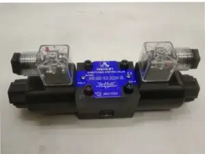
Solenoid Actuation: Uses electrical signals to shift the spool. A hydraulic solenoid valve enables remote control and automation.
Pilot Actuation: Uses hydraulic pressure to shift the main spool, ideal for high-flow applications.
Proportional Actuation: Provides variable control of flow and direction, enabling smooth acceleration and deceleration.
By Construction
Spool Valves: Use a sliding cylindrical spool to control flow—the most common type.
Poppet Valves: Use a poppet to seal against a seat, offering zero-leakage sealing.
Rotary Valves: Use rotary motion to control fluid flow.
5. How Does a Directional Control Valve Work with Hydraulic Cylinders?
The Directional Control Valve is the primary component for controlling hydraulic cylinders. The interaction between a Directional Control Valve and a cylinder is straightforward but critical to system operation.
Extending a Cylinder
When the operator moves the valve, the spool shifts, allowing pressurized fluid to enter the cap end of the cylinder. This forces the piston and rod to extend. The fluid on the rod side is pushed out and returns to the reservoir through the valve.
Retracting a Cylinder
When the Directional Control Valve is shifted to the opposite position, the spool redirects pressurized fluid to the rod end. This pushes the piston back, retracting the rod. The fluid from the cap end returns to the reservoir.
Stopping and Holding a Cylinder
When the Directional Control Valve is shifted to neutral, the spool blocks both cylinder ports, trapping fluid in the cylinder. This holds the cylinder in position. For this to work effectively, the valve must have low internal leakage.
6. Common Applications of Directional Control Valves
The Directional Control Valve is used across virtually every industry that relies on hydraulic power:
Construction Equipment: Excavators, loaders, and bulldozers use valves to control boom, bucket, and steering functions.
Industrial Machinery: Machine tools, presses, and injection molding machines rely on valves for precise motion control.
Agricultural Machinery: Tractors and harvesters use valves for implement control and steering.
Mobile Equipment: Forklifts and aerial work platforms use valves for lifting and positioning.
Oil and Gas: Valves control subsea systems and pipeline operations.
In each of these applications, the Directional Control Valve provides the control necessary for safe, efficient operation.
7. Selecting the Right Directional Control Valve
Choosing the correct Directional Control Valve for your application requires consideration of several factors:
Flow Rate: Determine the maximum flow the valve must handle.
Pressure Rating: The valve must be rated for the system’s maximum operating pressure.
Valve Type: Identify whether directional, pressure, or flow control is needed.
Actuation Method: Manual, solenoid, pilot, or proportional based on control needs.
Mounting Configuration: Subplate mounting, threaded, or cartridge style.
Center Type: Open, closed, tandem, or float center based on system requirements.
8. Maintenance and Troubleshooting
Proper maintenance of a Directional Control Valve is essential for reliable operation:
Keep Fluid Clean: Contamination is the leading cause of valve failure.
Check for Leaks: Inspect valve body and connections regularly.
Monitor Temperature: Excessive heat can damage seals and degrade performance.
Inspect Actuators: Ensure solenoids and manual operators are functioning properly.
Common issues with Directional Control Valves include sticking spools, internal leakage, and solenoid failure. Addressing these issues promptly prevents system downtime.
9. Future Trends in Directional Control Valve Technology
The hydraulic industry continues to evolve, with new technologies emerging:
Digital and Smart Valves: Built-in electronics and IoT connectivity for condition monitoring.
Energy-Efficient Designs: Minimizing pressure drops and reducing energy consumption.
Electrohydraulic Controls: Integration of electronic control with hydraulic valves for improved precision.
Conclusion
A Directional Control Valve is the control center of any hydraulic system, directing fluid flow, regulating pressure, and controlling actuator speed and direction. By understanding what a Directional Control Valve is and how it works, you can design, operate, and maintain hydraulic systems more effectively. Whether you need a hydraulic spool valve for smooth operation, a hydraulic solenoid valve for remote control, or a proportional valve for precise speed control, selecting the right Directional Control Valve is essential for reliable, efficient hydraulic system performance.