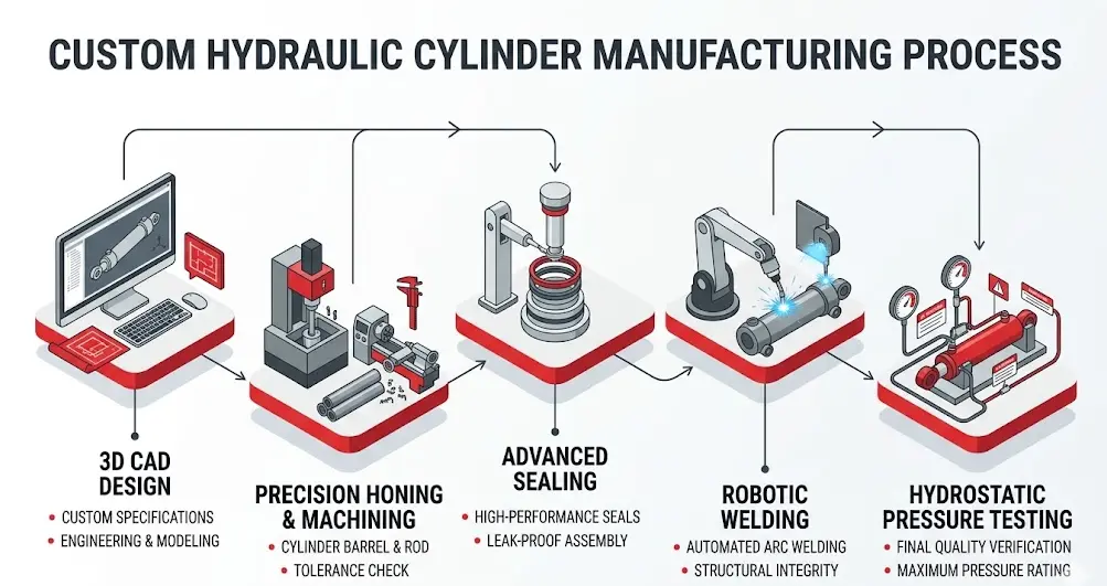
In the vast landscape of industrial machinery, standardized components often reach a point where they can no longer meet the demands of highly specialized applications. Whether it is an offshore drilling platform facing corrosive saltwater or a high-speed manufacturing line requiring micron-level precision, standard equipment frequently falls short. This is where customized fluid power solutions become essential. Developing these specialized components requires a deep understanding of mechanical engineering, metallurgy, and precision manufacturing. The actual hydraulic cylinder manufacturing process is an intricate journey that transforms raw steel billets into heavy-duty linear actuators capable of moving thousands of tons reliably.
For complex industrial machinery, selecting off-the-shelf parts often leads to premature failure or suboptimal performance. Investing in Custom Hydraulic Cylinders ensures that every dimension, seal material, and structural reinforcement aligns precisely with the unique operational pressures, environmental hazards, and duty cycles of the target application. Understanding this manufacturing process highlights the immense engineering effort required to ensure these critical components perform reliably under extreme conditions.
Phase 1: Engineering Design and Material Selection
The lifecycle of a specialized hydraulic cylinder does not begin on the factory floor; it starts within advanced computer-aided design (CAD) software. Engineers must carefully analyze the specific operational parameters provided by the client, including operating pressure, environmental temperature, stroke velocity, and potential side loads.
Through Finite Element Analysis (FEA), designers simulate real-world stresses on the cylinder structure before any metal is cut. This simulation identifies potential weak points in the rod, cap, or barrel, allowing engineers to optimize wall thickness and weld geometries for maximum safety and longevity.
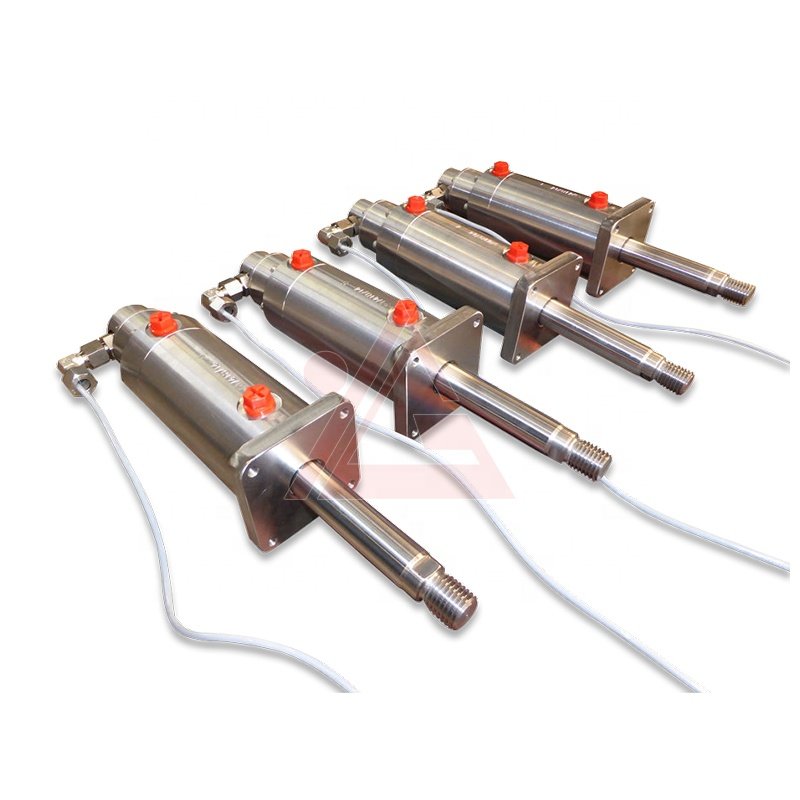
Material selection is equally vital during this initial stage. While standard carbon steel is suitable for benign indoor environments, harsher conditions demand specialized materials. For instance, when designing equipment for marine environments, chemical processing plants, or subsea applications, choosing a Stainless Steel Hydraulic Cylinder is crucial for preventing pitting, rust, and premature structural failure caused by corrosive elements. The steel grades chosen must offer the ideal balance of tensile strength, yield strength, and weldability.
Phase 2: Core Components Machining & Processing
Once the design blueprints are finalized and verified, the raw materials enter the machining phase. This phase is divided into separate, highly specialized workflows for the two primary structural elements: the cylinder barrel and the piston rod.
The Cylinder Barrel
The barrel serves as the pressure vessel that contains the high-pressure hydraulic fluid. It begins as seamless steel tubing, which undergoes a rigorous internal refining process. The two main techniques used to achieve the necessary internal surface finish are skiving and honing.
Skiving: A high-speed cutting process where specialized blades remove material from the internal diameter to establish precise concentricity.
Honing: A secondary abrasive process utilizing fine stones to polish the inner bore, creating a smooth, mirror-like finish with a cross-hatch pattern.
This cross-hatch pattern is essential because it retains a microscopic film of oil, lubricating the piston seals during operation and drastically reducing wear.
The Piston Rod
The piston rod transfers the linear force generated by the fluid to the external machinery. Because it is continuously exposed to external debris and structural loads, its surface finish and hardness are critical.
The rod is precision-turned on CNC lathes, ground to exacting tolerances, and then subjected to induction hardening. This hardening process creates a resilient outer layer that resists stone chips, impacts, and scratching. Following heat treatment, the rod undergoes hard chrome plating, which is polished to a flawless finish to ensure it does not damage the rod seals as it strokes in and out.
Adapting to Specialized Styles
The manufacturing steps adapt significantly based on the specific type of cylinder being built. For example, when a long stroke length is needed but space is highly constrained, the production line shifts focus toward a Telescopic Hydraulic Cylinder. This requires machining multiple nested steel sleeves, or stages, each fitting perfectly inside the next with incredibly tight tolerances to prevent binding.
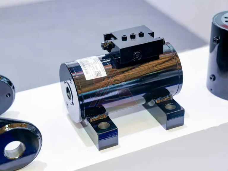
Conversely, if the application demands extreme structural integrity to withstand immense system pressures, the focus shifts to a High Pressure Hydraulic Cylinder. This variant requires much thicker barrel walls, specialized forged end caps, and reinforced port designs to manage heavy workloads safely.
Phase 3: Advanced Seals and Sensor Integration
A hydraulic cylinder is only as reliable as its sealing system. Without high-performance seals, internal fluid bypass or external leakage can quickly compromise system pressure and cause operational failure. Modern custom designs utilize a multi-stage sealing configuration:
Wiper Seal (Excluder): Scrapes dirt, dust, and moisture off the rod during retraction to protect internal components.
Rod Seal: The primary barrier that prevents hydraulic fluid from leaking out past the rod.
Buffer Seal: Sits behind the rod seal to absorb extreme pressure spikes and cushion the primary seal.
Piston Seals: Ensure fluid cannot pass from one side of the internal piston chamber to the other, maintaining steady directional force.
Wear Bands: Prevent metal-on-metal contact between the piston/gland and the barrel, absorbing side loads.
In addition to robust sealing, modern industrial automation requires real-world data tracking. This has led to the rise of smart cylinders. Manufacturers frequently integrate linear displacement transducers directly into the cylinder core. By drilling a deep, precise gun-bore down the center of the piston rod, a sensor probe can track the exact position of the rod in real time.
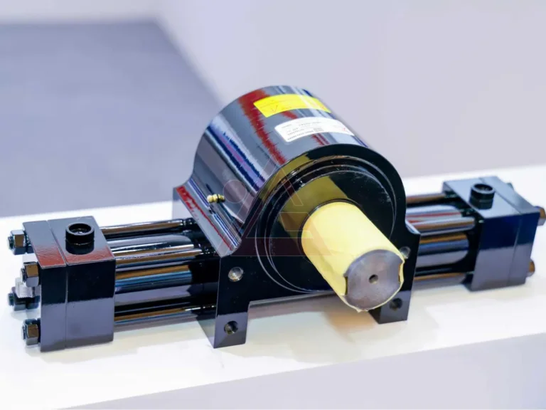
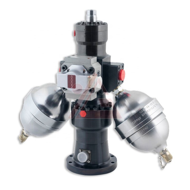
This level of precision control is essential for a Servo Hydraulic Cylinder, which works with electro-hydraulic servo valves to provide highly accurate position and force control in automated assembly lines, testing rigs, and aerospace simulators.
Phase 4: Welding and Assembly Procedures
With the individual components machined, treated, and fitted with appropriate seals, the cylinder moves to the welding and assembly stations. Welding the end caps, ports, and mounting flanges to the barrel requires exceptional precision, as any structural defect can cause catastrophic failure under high operating pressures.
Manufacturers utilize automated Gas Metal Arc Welding (GMAW) or Gas Tungsten Arc Welding (GTAW) systems to maintain consistent penetration and bead quality. For high-volume or ultra-precise requirements, friction welding is often employed, using rotational friction to fuse parts without adding filler metal. This creates an incredibly strong, seamless joint.
Following welding, all components enter a strictly controlled, clean-room assembly environment. Even microscopic dust particles trapped inside a cylinder can score the polished barrel walls or tear a seal, leading to premature failure. Skilled technicians assemble the piston, rod, seals, and gland using specialized torque tools to ensure every component is tightened to exact engineering specifications.
| Component | Primary Material Choices | Key Manufacturing Processes Involved | Critical Performance Metrics |
|---|---|---|---|
| Cylinder Barrel | Carbon Steel, ST52.3, E355, Stainless Steel | Skiving, Honing, Boring, Deep-hole drilling | Inner surface roughness ($R_a \le 0.4\ \mu\text{m}$), Concentricity |
| Piston Rod | 42CrMo4, C45E, Chrome-plated Stainless Steel | CNC Turning, Induction Hardening, Precision Grinding | Surface Hardness ($55\text{--}62\ \text{HRC}$), Plating Thickness |
| Sealing System | Polyurethane (PU), Nitrile (NBR), PTFE, Viton | Precision Injection Molding, Custom Machining | Low friction, Temperature range, Chemical compatibility |
| End Caps / Mounts | Forged Steel, Ductile Iron, Cast Steel | Forging, CNC Machining, Robotic Welding | Weld penetration, Tensile strength, Fatigue life |
Phase 5: Rigorous Testing and Quality Assurance
No custom cylinder leaves a world-class manufacturing facility without undergoing rigorous testing to verify its structural integrity and operational performance. Quality assurance is the most critical stage for validating the design and manufacturing choices made throughout the process.
The primary validation method is hydrostatic testing on a specialized hydraulic test bench. The cylinder is filled with fluid and pressurized well beyond its maximum rated operating capacity. This proof pressure test checks for structural deformation, weld weeping, and external seal leaks.
Technicians also perform internal bypass testing. By pressuring one side of the piston while keeping the opposite port open, they can measure if any fluid slips past the internal piston seals. This testing protocol ensures that the finished product adheres strictly to international safety and quality guidelines, such as those established by the International Organization for Standardization (ISO), guaranteeing dependable performance in demanding field operations.
Finishing, Coating, and Final Inspection
After passing all pressure and performance tests, the cylinder moves to the finishing department. The exterior of the cylinder is thoroughly blasted to remove any surface scale, oil, or welding residue. A high-durability primer is applied, followed by specialized industrial coatings designed to withstand harsh operating environments. For industrial applications, epoxy-based paints are common, while marine-grade coatings or offshore polyurethane topcoats are used for equipment exposed to heavy salt spray and weather.
Once the paint cures, the cylinder undergoes a final quality inspection. Technicians verify all critical external dimensions, stroke length, port alignments, and pin-hole configurations against the original CAD blueprints. Protective plugs are then installed into the fluid ports to prevent contamination during transport, and the completed assembly is carefully crated for shipping.
Conclusion
The custom hydraulic cylinders used in heavy machinery require a meticulous blend of precision engineering, advanced metallurgy, and strict quality control. From the initial 3D design and material selection to precision honing, specialized welding, and high-pressure testing, every step of the hydraulic cylinder manufacturing process plays a vital role in the reliability of the final product. Partnering with a dedicated manufacturer who understands these intricacies allows operations to secure fluid power solutions tailored specifically to their unique challenges, delivering reliable, long-term performance.
FAQ
What factors dictate the timeline of a custom hydraulic cylinders manufacturing run?
The delivery schedule depends on design complexity, raw material availability, and specific engineering requirements. Standardized configurations using common materials can be processed quickly. However, specialized builds—such as those incorporating multi-stage telescoping sleeves, integrated linear sensors, or specialized corrosion-resistant alloys—require extended machining, heat treatment, and testing phases, which naturally extend production timelines.
How does the hydraulic cylinder manufacturing process protect against internal seal failure caused by side-loading?
During the engineering phase, designers calculate expected side-loading forces and integrate specialized wear bands (often made of glass-filled nylon or bronze-filled PTFE) onto the piston and internal gland assemblies. These wear bands absorb lateral forces, preventing metal-on-metal contact between the rod and cylinder wall. This protects the primary pressure seals from uneven wear and tearing.
Can old or obsolete industrial cylinders be successfully replicated through custom manufacturing?
Yes. Through reverse engineering, technicians can disassemble an obsolete or worn-out cylinder, measure its core dimensions, map out the port configurations, and identify the structural materials used. Engineers then recreate the part in modern CAD software, allowing the factory to produce a brand-new component that drops directly into old machinery while incorporating modern seal technologies for improved performance.