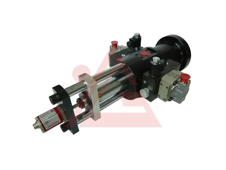
Selecting a hydraulic cylinder involves much more than calculating bore size and stroke length. A surprisingly high percentage of premature field failures stem not from internal pressure or seal defects, but from a mismatch between the machine’s movement and how the cylinder is physically anchored. The way a cylinder is held in place dictates how stress travels through its body, down the piston rod, and into the surrounding machine frame.
Choosing the appropriate hydraulic cylinder mounting arrangement requires balancing structural rigidity with mechanical flexibility. If a machine member moves along a curved path, forcing it to use a rigidly fixed cylinder will introduce massive side loads, bending the rod and tearing through seals. Conversely, allowing pivot movement where absolute straight-line precision is needed leads to buckling and structural instability. Finding the sweet spot between these forces ensures longevity and predictable machine behavior.
Why Hydraulic Cylinder Mounting Selection Matters
In an ideal engineering simulation, forces travel perfectly along the centerline of the piston rod. In the real world, tolerances shift, structural frames flex under load, and heavy components sag under gravity. These realities introduce side load, the primary enemy of any fluid power system.
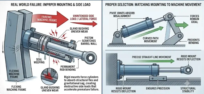
When a Standard Hydraulic Cylinders setup encounters unintended lateral forces, the internal bearing surfaces bear the brunt of the abuse. The piston scratches against the barrel wall, and the gland bushings wear unevenly. This creates a cascade failure: seals begin to weep, internal bypass lowers volumetric efficiency, and eventually, the rod bends permanently. Selecting the right mounting style mitigates these risks by either absorbing minor misalignments through pivoting joints or rigidly resisting deflection through heavy-duty fixed mountings.
Classifying Hydraulic Cylinder Mounts: The Three Main Families
Industrial and mobile applications generally categorize mounts into three primary architectural families. Each handles structural stress and directional forces in fundamentally different ways.
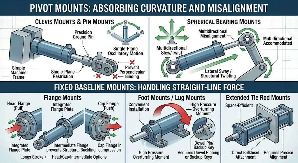
Pivot Mounts: Absorbing Curvature and Misalignment
Pivot mounts are designed for applications where the machine component travels through an arc or where structural flexing makes perfect alignment impossible. By allowing the cylinder body to swing, these mounts isolate the rod from destructive bending moments.
Clevis Mounts & Pin Mounts
The clevis mount features a dual-jaw bracket that encapsulates a single mating eye on the machine frame, secured by a precision ground pin. It is highly effective for heavy-duty oscillatory motion, such as the boom and bucket movements on earthmoving equipment. Because the pivoting action is restricted to a single plane, the entire assembly must be carefully aligned during installation to prevent binding along the perpendicular axis.
Spherical Bearing Mounts
When a machine cannot guarantee single-plane movement, spherical bearings—often integrated into the cap or rod end—provide the ultimate solution. These mounts allow for a few degrees of multidirectional misalignment, accommodating lateral sway or structural twisting without twisting the cylinder body itself. They are frequently utilized in heavy agricultural attachments and complex multi-link industrial linkages.
Fixed Baseline Mounts: Handling Straight-Line Force
Fixed mounts lock the cylinder body securely to a flat surface or bulkhead. These are the go-to choices when the workload moves along a strictly defined, guided straight path, demanding maximum structural stiffness.
Flange Mounts
Flange mountings utilize a heavy, machined plate integrated into the cylinder’s head (front), cap (rear), or an intermediate position along the barrel. Head flanges are ideal for pull applications because the mounting bolts experience simple compressive stress against the machine wall. Cap flanges, conversely, excel in heavy push applications. Intermediate flanges provide a middle ground, shortening the unsupported length of long-stroke cylinders to prevent structural buckling.
Foot Mounts / Lug Mounts
Foot mounts consist of heavy tabs or brackets welded or bolted to the ends of the cylinder, allowing it to sit flat on a mounting base parallel to the cylinder centerline. While highly convenient for installation, side lugs experience a substantial overturning moment under high pressure. The force of the stroke tries to lift the cylinder off its mounting surface, requiring robust dowel pinning or backup keys to shear-proof the assembly against high-impact loads.
Extended Tie Rod Mounts
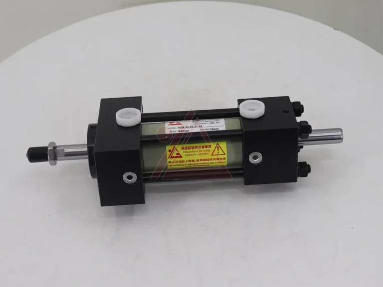
Commonly found in standard National Fluid Power Association (NFPA) industrial tie-rod cylinders, this style extends the structural tie rods beyond the head or cap of the cylinder. The extended rods then pass directly through the machine’s mounting bulkhead and are secured with heavy hex nuts. It is an exceptionally space-efficient, clean-looking mounting method best suited for compact industrial automation machinery, though it requires precise hole alignment in the receiving plate.
Comparing Top Mounting Types: Pros, Cons, and Best Uses
To assist in the initial engineering screening process, the following matrix contrasts the performance attributes of the most widely applied industrial mounting configurations.
| Mounting Category | Specific Style | Primary Force Direction | Misalignment Tolerance | Best Production Application |
|---|---|---|---|---|
| Pivot | Clevis / Pin | Axial (Allows multi-plane rotation) | Low (Single plane only) | Excavator booms, dump beds, scissor lifts |
| Pivot | Spherical Bearing | Axial (Allows multi-axis sway) | High (Accommodates structural twist) | Mining haulers, articulated steering joints |
| Fixed | Cap Flange | Compression (Pushing applications) | Zero (Requires guided paths) | Heavy stamping presses, plastic injection molds |
| Fixed | Head Flange | Tension (Pulling applications) | Zero (Demands strict centerline precision) | Material extraction rams, industrial die pullers |
| Fixed | Side Foot / Lug | Shear / Parallel Axial | Zero (Prone to turning moments) | Long-stroke industrial balers, conveyor transfers |
Key Factors to Consider When Selecting a Mount
An operational mismatch often happens when a mount is chosen out of habit rather than calculated necessity. To avoid unexpected machine downtime, several intertwined design criteria must be thoroughly evaluated.
Direction of Force & Load Path
The golden rule of fluid power engineering is to align the mounting support as closely as possible with the centerline of the force application. If a foot mount is bolted down parallel to the load line, it inherently creates a lever arm equal to the distance from the cylinder centerline to the mounting plate. Under a 3,000 PSI spike, this lever arm generates massive bending stresses. Flanges and tie-rod extensions, by contrast, pull or push directly along the centerline, converting high hydraulic pressures into pure tensile or compressive stresses which metals handle far more efficiently.
Operating Speed and Cycle Frequency
High-cycle applications, such as high-speed sorting gates or automated stamping lines, generate constant vibration and harmonic resonance. Fixed mountings in these environments are prone to fatigue failure at the weld joints or mounting bolts if not oversized appropriately. Pivot mounts used in high-frequency applications require continuous lubrication interfaces—such as greased bronze bushings or hardened steel pins—to prevent galling and severe back-lash over millions of operational cycles.
Structural Integrity & Space Constraints
In compact machinery housings, there may simply not be enough physical clearance to accommodate a massive front flange or wide side lugs. In these instances, spatial limitations dictate the use of extended tie rods or integrated rear trunnions. Furthermore, long-stroke cylinders acting horizontally require intermediate support to counteract the natural sagging weight of the extended steel piston rod.
Custom vs Standard Requirements
While catalog-standard mounts handle the vast majority of factory floors, highly specialized heavy machinery often demands tailored solutions. When dealing with extreme environments like marine subsea operations, steel mill casting floors, or ultra-compact defense applications, a standard commercial bracket will quickly fail. In these severe scenarios, collaborating with engineering teams to design Custom Hydraulic Cylinders ensures that the mounting geometry, material chemistry, and pin tolerances are perfectly optimized for the unique operating stresses of the environment.
Maintenance and Prevention of Mounting Failures
Walk through any industrial facility or construction site and you will eventually spot a hydraulic cylinder weeping oil around its rod gland. Look closer at the mounting brackets, and you will often find the root cause: a missing cotter pin, a loose flange bolt, or a dry, unlubricated pivot joint that has seized solid.
When a mounting bolt loses its torque tension, the cylinder begins to shift slightly with every cycle. This minute movement, known as micro-fretting, rapidly deforms the mounting holes and shifts the load off-center. What began as a 0.05-inch misalignment escalates into a severe side load that destroys internal seals within weeks. Preventative maintenance programs must include routine torque checks on all fixed mounting fasteners and regular grease intervals for pivot points. If a pivot pin cannot move freely, the cylinder effectively transforms into an improperly aligned fixed mount, inviting catastrophic structural failure.
Conclusion
Every successful fluid power application relies on a secure, stable installation. Choosing the correct hydraulic cylinder mounting configuration requires looking beyond simple space constraints to understand the complex mechanical forces at play during peak operation. By matching the structural rigidity of fixed flanges or the flexible compliance of pivot pins to the actual path of your machine’s workload, you protect internal seals, eliminate rod deflection, and significantly extend the operating life of your hydraulic equipment.
FAQ
What are the main indicators that a hydraulic cylinder mounting style is mismatched to the machine?
The most telling signs include rapid, uneven wear on the piston rod’s chrome plating, recurring oil leaks at the front rod seal despite frequent replacements, and loose or fractured mounting bolts. If you notice the cylinder body flexing or binding visibly during its stroke, it indicates that side loading forces are overpowering the current mounting architecture.
Can I weld a standard foot mount directly to my machine frame to eliminate loose bolts?
While welding eliminates the risk of bolts backing out under vibration, it is generally discouraged unless specified by the manufacturer. The intense heat of field welding can distort the precision-honed cylinder barrel, ruin internal seals, and alter the heat treatment of the steel. It also makes future maintenance and component replacement exceptionally difficult. If welding is required, use pre-engineered weldable brackets or intermediate trunnion rings designed for that purpose.
How does a trunnion mount differ from a standard clevis pin mount?
While both are pivot mounts designed to handle curved motion paths, a clevis mount is located at the very tip of the cylinder cap or rod end. A trunnion mount utilizes heavy cylindrical pins extending outward from the sides of the cylinder body. Trunnions can be positioned at the head, cap, or midway along the barrel, allowing designers to alter the leverage pivot point and balance the physical weight of long-stroke cylinders more effectively.